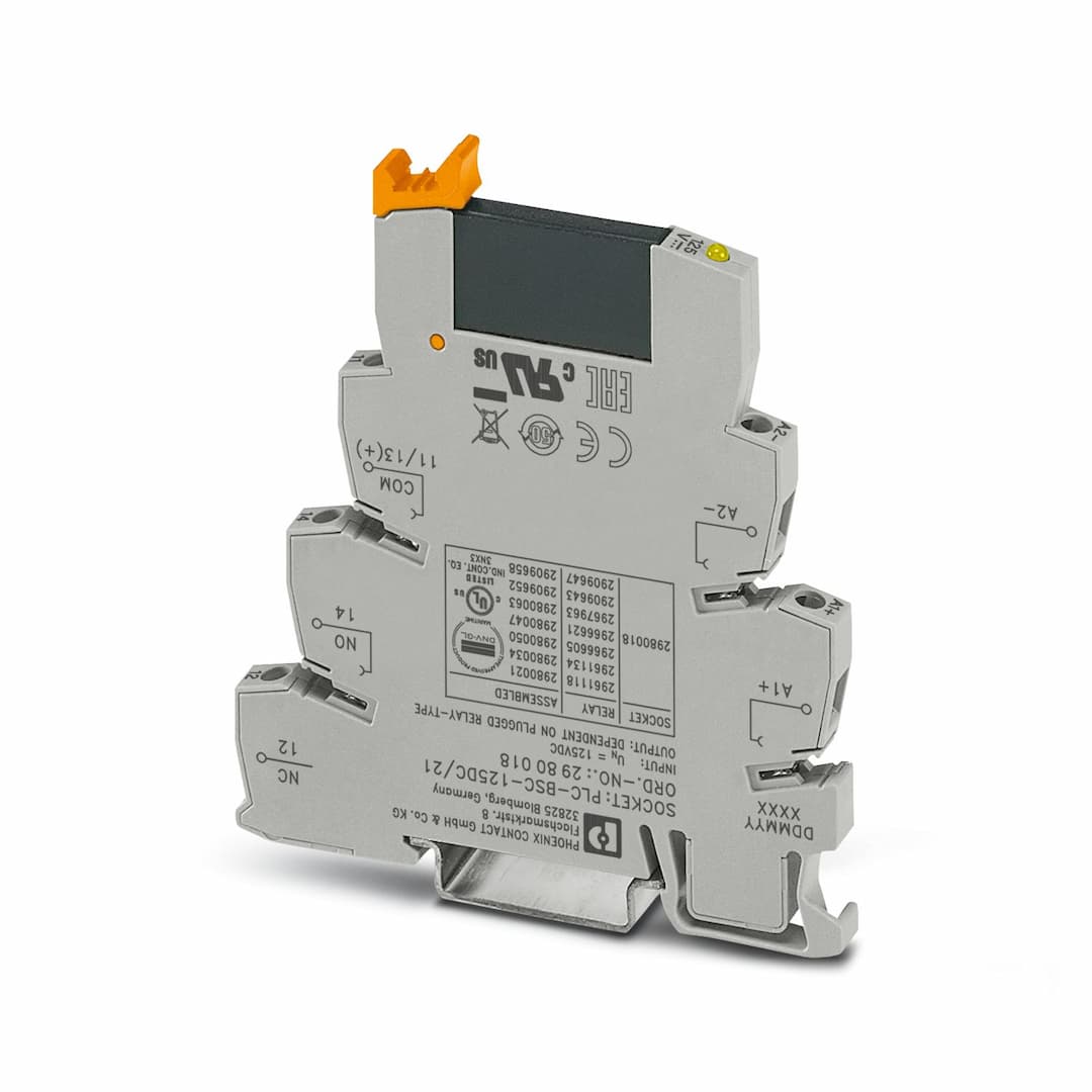
Product Model
PLC-OSC-125DC/ 24DC/ 2

Key Features
- 1Slim design for compact installations.
- 2Efficient connection to system cabling using V8 adapter.
- 3RT III sealed solid-state relays for durability.
- 4Integrated input circuit for simplified setup.
- 5Reliable performance in various industrial applications.
Technical Specifications
Detailed engineering parameters based on manufacturer documentation
| Parameter | Value | Parameter | Value |
|---|---|---|---|
| Product type | Solid-state relay module | Product family | PLC-INTERFACE |
| Application | Universal | Operating mode | 100% operating factor |
| Date of last data management | 07.05.2024 | Article revision | 07 |
| Insulation | Basic insulation | Overvoltage category | III |
| Pollution degree | 2 | Maximum power dissipation for nominal condition | 0.38 W |
| Test voltage (Input/output) | 2.5 kV (50 Hz, 1 min., input/output) | Nominal input voltage U | 125 V DC |
| Nominal voltage (plugged-in solid-state relay) | 60 V DC | Input voltage range in reference to U | 0.8 ... 1.1 |
| Input voltage range | 100 V DC ... 137.5 V DC | Switching threshold "0" signal in reference to U | ≤ 0.3 |
| Switching threshold "1" signal in reference to U | ≥ 0.8 | Typical input current at U | 3 mA |
| Typical response time | 40 µs (at U | Typical turn-off time | 600 µs (at U |
| Operating voltage display | Yellow LED | Protective circuit | Reverse polarity protection; Polarity protection diode |
| Transmission frequency | 100 Hz | Contact switching type | 1 N/O contact |
| Design of digital output | electronic | Output voltage range | 3 V DC ... 33 V DC |
| Limiting continuous current | 3 A (see derating curve) | Maximum inrush current | 15 A (10 ms) |
| Voltage drop at max. limiting continuous current | ≤ 200 mV | Output circuit | 2-conductor, floating |
| Protective circuit | Reverse polarity protection; Polarity protection diode
Surge protection | Connection method | Screw connection |
| Stripping length | 8 mm | Screw thread | M3 |
| Conductor cross section rigid | 0.14 mm² ... 2.5 mm² | Conductor cross section flexible | 0.14 mm² ... 2.5 mm²
0.2 mm² ... 2.5 mm² (Single ferrule)
2x 0.5 mm² ... 1.5 mm² (TWIN ferrule) |
| Conductor cross section AWG | 26 ... 14 | Tightening torque | 0.6 Nm ... 0.8 Nm |
| Width | 6.2 mm | Height | 80 mm |
| Depth | 94 mm | Color | gray (RAL 7042) |
| Flammability rating according to UL 94 | V0 (Housing) | Ambient temperature (operation) | -25 °C ... 60 °C |
| Ambient temperature (storage/transport) | -25 °C ... 70 °C | Certificate | CE-compliant |
| Certificate | UKCA-compliant | Certificate | TAE0000196 |
| Identification | ISA-S71.04. G3 Harsh Group
EN 60068-2-60 | Temperature | D |
| Humidity | A | Vibration | B/C |
| EMC | B | Enclosure | Required protection according to the Rules shall be provided upon installation on board |
| Electromagnetic compatibility | Conformance with EMC directive | Low Voltage Directive | Conformance with Low Voltage Directive |
| Standards/regulations | IEC 60947-5-1 | Mounting type | DIN rail mounting |
| Assembly note | in rows with zero spacing | Mounting position | any |
Specifications may be subject to change without notice
